
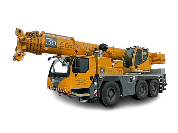
When operating heavy lifting equipment, downtime translates directly into revenue loss. Liebherr mobile and crawler cranes—such as the LTM, LTC, and LR series—rely on the proprietary Liebherr Computed Control (LICCON) system for real-time load monitoring, safe load indicators (SLI/LMB), boom positioning, and engine performance diagnostics.
When a LICCON display monitor goes blank or a control card experiences hardware breakdown, replacing the entire modular assembly through OEM channels can cost tens of thousands of dollars and take weeks to ship.
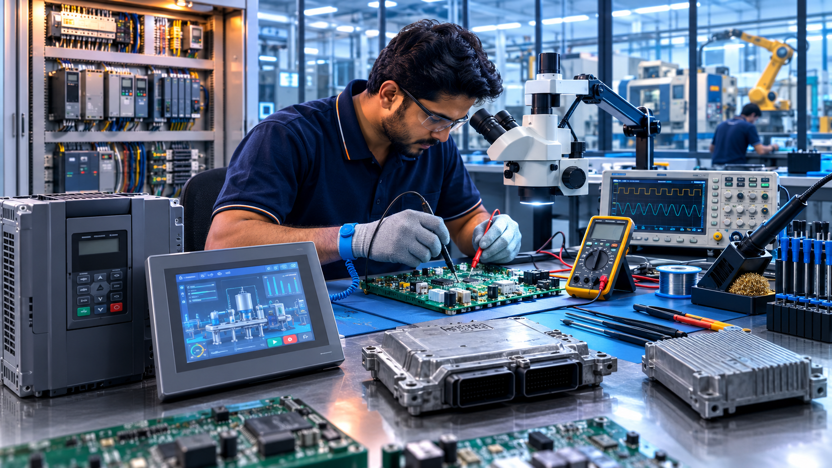
At Soham Technologies, we specialize in component-level electronic repair, precision display monitor fixing, and PCB rebuilding for complex industrial machinery and heavy cranes. Below is an exhaustive technical breakdown of how LICCON control systems function, common error modes, board-level failure diagnostics, and how advanced repair services keep your fleet fully operational.
1. Understanding the Architecture of the Liebherr LICCON System
The LICCON platform (spanning LICCON 1, LICCON 2, and the modern LICCON 3 architectures) operates on a distributed Controller Area Network (CAN-bus) and LIEBHERR System Bus (LSB) infrastructure.
+-----------------------------------------------------------------------+
|                       LICCON Monitor / Display Unit                   |
|                   (BSE Master / Operator Interface)                   |
+-----------------------------------------------------------------------+
                                   |
                         [ High-Speed LSB / CAN ]
                                   |
  +--------------------------------+--------------------------------+
  |                                |                                |
+-----------------------+  +-----------------------+  +-----------------------+
|  Main Central Unit    |  |  Universal I/O Cards  |  |  Power & Driver Board |
| (ZE / Processor Card) |  |   (UEA Modules / LSB) |  |   (Solenoid Drivers)  |
+-----------------------+  +-----------------------+  +-----------------------+
Key Electronic Assemblies inside the System:
- BSE Master & Monitor Display Unit: The primary human-machine interface located in the crane operator cabin. It houses display controllers, graphics processors, membrane keypad boards, and backlighting inverters.
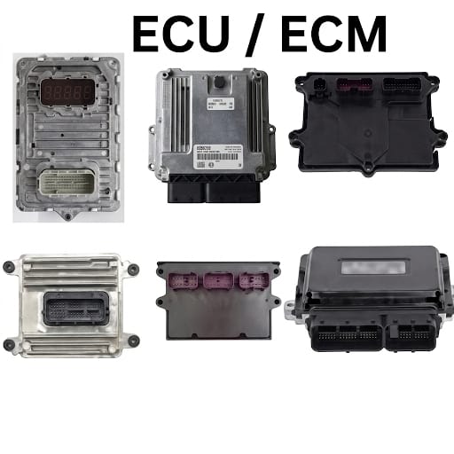
- Central Logic / Processor Card (ZE Card): The core computing board executing control routines, calculating load charts, and managing safety interlocks.
- Universal Input/Output Modules (UEA Cards): Signal processing cards that read analog and digital inputs from length sensors, angle sensors, pressure transducers, and hoist limit switches.
- Bus Communication Transceivers: Hardware responsible for differential data transmission between the chassis (UW) and superstructure (OW).
When any of these printed circuit board assemblies (PCBAs) degrade, the system triggers safety lockouts, stopping crane movements instantly to prevent accidents.
2. Common Failures in Liebherr LICCON Systems & Visual Error Signals
Electronic components on heavy cranes face extreme operation conditions, including intense mechanical vibration, thermal cycling, moisture ingress, and DC power spikes from heavy alternator loads.
       +---------------------------------------------------------+
       |               LICCON SYSTEM FAILURE MODES               |
       +---------------------------------------------------------+
                                    |
     +------------------------------+------------------------------+
     |                              |                              |
+--------------------------+  +--------------------------+  +--------------------------+
|  Display & Visual Defects|  | PCB & Hardware Failures  |  | Bus & System Errors      |
|  - Blank / White Display |  | - Power Converter Spikes |  | - CAN-Bus Timeout        |
|  - Touch / Keypad Faults |  | - Blown Capacitors / ICs |  | - Sensor Signal Loss     |
|  - Backlight Inverter    |  | - Corroded Copper Traces |  | - Watchdog Memory Errors |
+--------------------------+  +--------------------------+  +--------------------------+
A. Monitor Display & Graphics Failures
- Screen Blackout or Frozen Display: Power supply failure inside the monitor housing or micro-controller execution failure on the graphics driver card.
- Fading / Flicker / White Screen: Degraded cold cathode fluorescent lamp (CCFL) inverters or failing LED backlights within older LICCON 1 monitor units.
- Unresponsive Keypads & Touch Interfacing: Fractured membrane switches, corroded flex ribbon cables, or damaged touch controller ICs.
B. Board-Level Hardware & Control Card Failures
- ZE Watchdog / Memory Errors: Microprocessor timing errors, corrupted Flash/EPROM memory, or broken solder balls beneath surface-mount chips.
- Burnt Output Drivers: Transistor or MOSFET breakdowns on solenoid driver cards caused by short circuits in hydraulic valves.
- Voltage Regulator Collapse: Blown tantalum capacitors, shorted diodes, or burned power Management ICs (PMICs) caused by improper jump-starting of the crane’s engine.
3. Step-by-Step Technical Repair Process at Soham Technologies
Replacing a main control board or display panel with a factory-new module is unnecessary when individual micro-components can be restored. At Soham Technologies, our engineers follow a thorough component-level diagnostic and rebuild workflow:
+-----------------------------------------------------------------------+
| STEP 1: Diagnostic Ingestion & Visual Micro-Inspection               |
| Check for burnt traces, shorted capacitors, heat stress, oxidation.   |
+-----------------------------------------------------------------------+
                                   |
                                   v
+-----------------------------------------------------------------------+
| STEP 2: In-Circuit Component Testing & Analysis                       |
| Utilize oscilloscopes, curve tracers, and thermal imaging cameras.    |
+-----------------------------------------------------------------------+
                                   |
                                   v
+-----------------------------------------------------------------------+
| STEP 3: Surface-Mount Desoldering & IC Replacement                    |
| Micro-soldering of damaged chips, driver ICs, transceivers, & caps.   |
+-----------------------------------------------------------------------+
                                   |
                                   v
+-----------------------------------------------------------------------+
| STEP 4: Display & Interface Restoration                              |
| LCD matrix replacement, backlight inverter rebuilding, flex repair.  |
+-----------------------------------------------------------------------+
                                   |
                                   v
+-----------------------------------------------------------------------+
| STEP 5: Bench Testing, CAN-Bus Validation & Conformal Coating          |
| Simulated signal testing followed by protective moisture sealing.    |
+-----------------------------------------------------------------------+
Detailed Bench Diagnostic & Repair Protocol:
- Visual & Thermal Inspection: The board is removed under ESD-safe protocols and inspected under high-magnification microscopes. Thermal imaging cameras pinpoint shorted surface-mount capacitors drawing excessive current.
- In-Circuit Component Signature Analysis: Specialized curve tracers check the integrity of input/output pins, logic gates, and bus transceivers without desoldering unnecessary parts.
- Precision Micro-Soldering: Damaged microcontrollers, CAN transceivers, power MOSFETs, and SMD capacitors are replaced using temperature-controlled hot-air rework stations.
- Display Panel Reconstruction: Defective display panels undergo panel replacement, digitizer swap, and high-voltage inverter repair to restore original screen clarity and touch responsiveness.
- Conformal Seal & Environmental Protection: Once validated, the repaired printed circuit board is coated with high-grade conformal coating to safeguard against moisture, hydraulic oil, dust, and continuous vibration.
5. Why Partner with Soham Technologies for Industrial & Crane Electronics Repair?
- Component-Level Expertise: We repair the original electronic cards instead of forcing costly total assembly replacements.
- Drastic Cost Reduction: Save 60% to 80% compared to buying brand-new OEM control units or replacement monitor panels.
- Rapid Turnaround Times: Minimize operational downtime caused by long OEM lead times for imported crane spare parts.
- Rigorous Testing Standards: Every repaired monitor, central logic card, and UEA module undergoes extensive bench tests before delivery.